Fiber optic cable pulling tension is a cable-specific installation limit, not a number that can be safely borrowed from a different cable or treated as the cable’s breaking strength. Before a duct pull, match the exact cable model to its current data sheet, document the route and pulling method, and set up equipment that can monitor and control the load. The crew also needs clear stop rules for a rising or unstable pull.
Quick answer: use the manufacturer’s maximum pulling tension for the selected cable and installation condition. Then have the responsible project engineer or qualified installer evaluate the actual route, bends, duct condition, cable fill, pulling attachment, lubricant, and equipment. A route calculation and a tension-controlled puller help manage the job, but neither replaces the cable maker’s limit or the approved project method. There is no one universal safe tension for all fiber optic cables.

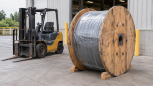
Illustrative cable-reel scene only; it does not depict a FiberCableSupplier product, shipment, or customer project. Photo by Boris Misevic via Unsplash.
In this guide
What pulling tension means
Pulling tension is the longitudinal force applied to move a cable through a route during installation. The limit in a cable data sheet applies to a stated cable construction and installation method. It is not automatically the same as the cable’s tensile strength, breaking load, long-term working load, or the rating of an individual strength member. Those terms describe different design or test conditions. Use the exact definition supplied by the cable manufacturer and the project documents.
This distinction matters because cable assemblies contain several materials that share load differently. Fibers carry the optical signal; strength members and other structural parts are designed to handle mechanical loads according to the cable design. A pulling attachment may engage a strength member, a dedicated pulling eye, or another manufacturer-approved feature. Pulling on an unapproved part can transfer load into a jacket or internal components in a way the cable was not designed to accept.
Maximum pulling tension also does not tell the whole story about a duct pull. At a bend, the cable presses against the route surface while under tension. The resulting sidewall pressure depends on the cable load and the bend geometry, among other inputs. A pull may therefore need review for both the permitted longitudinal tension and the route’s bend conditions. Corning’s engineering note, Pulling Fiber Optic Cable in Conduit, treats tension, bends, fill, jamming, and sidewall pressure as connected planning considerations.
Find the limit for the exact cable
Start with the complete cable designation, not a broad family name such as “outdoor fiber.” Confirm fiber count, cable construction, armor or other reinforcement, jacket, outside diameter, and installation type. Similar-looking cables may use different structural designs and can have different handling instructions. The data sheet must match the item being ordered and installed, and its revision should be recorded in the submittal or method statement.
Look for the maximum pulling tension and read any footnotes or installation notes attached to it. Check the unit, the test or installation condition, and whether the limit assumes a particular grip or pulling method. If the manufacturer publishes separate values for different configurations, use the value for the actual configuration. Do not convert a breaking-strength figure into a permitted installation tension unless the manufacturer or responsible engineer explicitly provides that relationship.
The cable’s bend-radius values must be reviewed separately. Some data sheets distinguish installation from operation; terminology varies. The fiber optic cable bend-radius guide explains why the pulling condition and final installed condition should not be conflated. A cable may satisfy its longitudinal tension limit while still encountering an unacceptable bend or sidewall pressure. Conversely, a generous bend does not authorize exceeding the maximum pull load.
Confirm whether the cable maker names a permitted pulling grip, pulling eye, swivel, lubricant, or tension-monitoring approach. Corning’s Duct Installation of Fiber Optic Cable procedure is an example of manufacturer guidance that calls for checking the cable specification and using suitable attachment and pulling practices. The procedure applies to the products and conditions it covers; it should not be treated as the specification for every cable brand or design.
Inputs for a duct-pull plan
A calculation or pull-plan review is only as useful as its inputs. Gather a route drawing and walk the pathway where practical. Record changes in direction, handholes, manholes, vertical sections, conduit transitions, known obstructions, and the locations where the crew can safely stage equipment. Include both permanent route features and temporary rollers or sheaves that will touch the cable during the pull.
| Input | Why it matters | What to document |
|---|---|---|
| Cable identity | The mechanical limit is specific to the cable design | Full model, construction, outside diameter, data-sheet revision |
| Route geometry | Length and bends affect the pull and cable contact | Section lengths, bend locations, direction changes, elevation changes |
| Duct condition | Actual pathway conditions affect friction and passage | Duct material and size, known damage, cleanliness, transitions |
| Fill and occupancy | Existing cables and available space can affect passage or jamming | Existing cable count and sizes, spare duct capacity, verified route |
| Pulling method | Equipment and attachment determine how load reaches the cable | Winch or hand method, grip, swivel, lubricant, monitoring method |
| Work coordination | Communication and staging influence response to a changing pull | Operator roles, stop signal, access points, emergency contacts |
Identify who owns each input. The designer may supply the route geometry, the contractor may verify duct condition, and the cable manufacturer may confirm the cable-specific limit and grip. If the available route information is only a schematic, label assumptions clearly and have the field team verify the pathway before cable is committed to the pull. Unknown bends or damaged conduit should be treated as unresolved conditions, not silently replaced by optimistic estimates.
Review a fiber optic cable pulling tension calculation
Do not assume that a single route length predicts the maximum load. Duct friction, changes in direction, fill, cable weight, route condition, and the pulling arrangement can affect the result. A route with a few well-understood bends can behave differently from one with a smaller number of tight transitions or an obstruction. A calculation should reflect the actual section sequence and the cable and duct properties used for the project.
For a fiber optic cable pulling tension review, have a qualified person check the calculation method, assumptions, and output against the selected cable’s limit. Use the cable manufacturer’s engineering guidance or an appropriate pull-calculation tool when the route warrants it. Corning’s engineering note discusses calculation topics such as cable fill and sidewall pressure; it does not make a generic number safe for every cable. The calculation should identify the expected peak-load location, the assumptions that most affect it, and whether the proposed pulling method remains within the approved limit.
Pay particular attention to the bend sections. A bend can increase cable contact force, and a smaller radius can raise sidewall pressure for a given load. The pulling plan should therefore assess both the route geometry and the longitudinal load. If the calculation reports a result close to the cable’s stated maximum, do not treat the limit as an operational target that the crew should reach. Ask the responsible engineer to review the assumptions and determine whether the route, pull direction, equipment, or sectioning should change.
Consider whether the pull should be divided or assisted. A mid-pull access point, a different pull direction, an intermediate setup, or route correction may reduce uncertainty, but each change also creates new handling steps and cable-contact points. The decision belongs in the engineered method statement. It should state how the cable is supported at each stage, which load is monitored, how the grip is transferred if needed, and what limits apply to each pull segment.
Review more than the predicted final number. Confirm the sensitivity to uncertain inputs such as friction, duct condition, route bends, and fill. If a modest change to an assumption causes the result to approach or exceed the cable limit, the plan needs better field information or a safer installation arrangement. Document the source of each input and identify which ones must be confirmed during the route walk. A calculation should reduce uncertainty, not hide it behind a precise-looking output.
Choose the pulling attachment for the cable design
The puller transfers load through an attachment, so verify that the cable maker permits the selected attachment for the exact construction. Some cable designs provide a pulling eye or a designated strength member for this purpose. Others may use an approved mesh grip or another specified method. Do not grip the jacket or connect a winch to a convenient part of the cable unless the manufacturer’s instructions explicitly allow it.
Check the attachment’s size and installation instructions. A grip that is too loose can slip; one that is installed incorrectly can concentrate force or damage the jacket. The attachment should align with the cable and pulling line so that it does not introduce unnecessary twist or sharp bending. Use only compatible components with documented capacity and a method that keeps the cable within its permitted loading condition.
A swivel may be required or recommended by the cable manufacturer and installation procedure to limit torsional transfer from the pulling line. Its use does not correct an incompatible grip, a poor route, or an excessive load. Confirm that the swivel, grip, and puller are compatible as one assembly. Inspect the connections before the pull and make sure the crew understands which components can rotate and which must remain aligned.
Before starting, have the designated person check the attachment against the cable instructions and confirm the cable end is prepared as specified. Protect the cable from exposed strands, sharp metal, or edges at the pulling head. Keep connectorized ends protected and outside the loaded pulling assembly unless the approved method is specifically designed for that assembly. The intent is not to improvise a stronger connection, but to apply the load through the part of the cable designed to take it.
For project-specific product selection, identify the required route, cable construction, fiber count, and installation method before requesting a quote. FiberCableSupplier’s fiber optic cable product range is a starting point for matching a cable family; request the data sheet and approved installation instructions for the exact model under consideration. A product page is not a substitute for the mechanical specification used by the field crew.
Set up monitoring and equipment
For a powered pull, select equipment that can control the load and provide a meaningful tension reading for the planned method. Confirm the device is suitable for the job, its working range is appropriate, its maximum-tension control is configured by a qualified operator, and its calibration or verification status is current according to the equipment owner’s procedure. A display that is difficult to read, outside its operating range, or not visible to the person controlling the pull is not an effective control.
Before the pull, check the sensor and readout, confirm the units, and verify that the display responds as expected using the equipment manufacturer’s procedure. Make sure the system can stop or limit the pull when the approved threshold is reached. If the project relies on a separate load cell or dynamometer, confirm its position in the load path and that the reading corresponds to the force applied through the cable attachment. Record the instrument identifier and the check performed when the project’s quality procedure requires it.
Set the operational stop point below the cable’s maximum only as directed by the responsible engineer or the approved method statement. The margin should reflect the project calculation, equipment behavior, measurement uncertainty, and response time; there is no universal percentage that can be applied to every pull. Ensure the puller’s maximum-tension control is not set above the approved plan. If the equipment cannot control or show tension adequately for the planned job, select another method before installation.
Agree on roles and communications. One person should control the puller, while designated crew members watch the reel, cable path, and access points. Use a radio channel or agreed signals that can stop the operation immediately. Test the communication plan before loading the cable. Every crew member should be authorized to call a stop if they see a snag, unexpected movement, cable twist, damaged guide, abnormal sound, or an unsafe condition.
A seven-step field procedure
1. Confirm cable identity and approved limits
Match the reel label to the cable schedule and the approved data sheet. Review the maximum pulling tension, bend requirements, temperature conditions, and permitted attachment. Check the document revision and resolve any mismatch before the cable is loaded. The crew lead should have the relevant page or method statement available at the worksite, not only in a remote submittal folder.
2. Walk the route and verify assumptions
Inspect the duct route and identify bends, transitions, handholes, access constraints, existing occupants, obstructions, and potential cable-contact points. Compare the field condition with the plan. Check the entry and exit edges, not only the mid-run duct. Record unresolved conditions and have the responsible person decide whether the pull should be redesigned, cleaned, divided, or held.
3. Install and inspect guides and pulling hardware
Place guides, rollers, sheaves, and entry protection so the cable path follows the approved geometry. Verify that each component is secured, aligned, and compatible with the cable and route. Inspect the pull line, grip, swivel, and connectors. Confirm the cable can be paid off from the reel in the intended direction without uncontrolled turns or contact with sharp edges.
4. Check the monitoring and stop controls
Verify the tension display, units, control setting, and stop function according to the equipment procedure. Make sure the operator who controls the pull can see the reading and respond to it. Test communications between the puller, reel, and access-point teams. Review the stop signal, the approved limit, and the person responsible for recording the pull.
5. Start slowly and observe the cable path
Begin in a controlled way under the approved method statement. Check for smooth reel payoff, movement through the first transition, and any sudden rise in the tension reading. Confirm the cable remains in its guides and does not twist, snag, ride over a flange, or scrape an unprotected edge. Do not accelerate until the crew has verified that the initial part of the pull is stable.
6. Monitor, communicate, and stop on the agreed triggers
Keep the reading and the route under active observation. Stop if the load reaches the approved stop point, rises unexpectedly, becomes unstable, or the monitoring system fails. Also stop for a suspected snag, a displaced guide, loss of communication, visible cable damage, or any condition that differs from the plan. Never compensate for a stalled pull by simply applying more force. Investigate the route and get authorization before resuming.
7. Inspect, document, and hand over
After the cable is placed, inspect accessible sections, entry points, stored slack, and supported transitions. Confirm that the installed route respects the cable’s applicable operating bend requirements and that ties or supports do not crush the cable. Save the tension record, note the route and reel identification, record any deviation, and complete the project’s acceptance tests. A test result complements the installation record; it does not replace the mechanical checks.
Conditions that can change the pull
Bends and sidewall pressure: route bends influence cable contact and load. Confirm the bend radius against the exact cable requirement and have the pull calculation address sidewall pressure where applicable. A route that appears to fit on a drawing may contain a tighter field transition at a duct mouth, handhole, or building entry.
Duct fill and jamming: existing cables and the incoming cable share limited space. The arrangement and relative sizes may affect whether the cable can move through a bend without becoming trapped. Verify actual occupancy and follow an appropriate calculation method. If the route is already congested or its existing contents are uncertain, ask for engineering review instead of assuming the empty-duct result applies.
Friction, contamination, or damage: debris, standing water, deformation, sharp transitions, or other pathway conditions may cause behavior that differs from the calculation assumptions. Inspect and prepare the duct according to the project method. If the pull begins to behave differently than expected, stop and investigate. The crew should not interpret a steady motor sound as proof that the cable load is within its limit.
Lubricant and temperature: use a lubricant only when the cable and lubricant manufacturers or approved method permit it, and confirm compatibility. Follow cable temperature limits during installation and storage. Cold or hot conditions may change handling requirements; do not assume that a lubricant or pulling procedure approved for another product is suitable here.
Pay-off and crew coordination: reel orientation, braking, line alignment, and communication between access points all influence the operation. A reel that does not pay off smoothly can introduce additional handling stress. Keep the cable under control, prevent uncontrolled loops, and use the agreed stop signal if any crew loses sight of the cable or cannot communicate with the puller.
More detail on receiving, moving, storing, and paying off a reel is available in the fiber optic cable drum handling and storage guide. Pull planning also connects to quantity and route planning; see the fiber optic cable procurement planning guide for project information to organize before an order. These resources address adjacent stages and should be used alongside the manufacturer’s installation instructions.
What to do after a tension event
If the reading reaches the stop point, rises unexpectedly, or the crew suspects a snag or shock load, stop the operation using the approved procedure. Do not immediately resume just because the cable is still moving or the jacket looks normal. Record what happened, including the route location, reading and units, equipment state, time, cable reel or lot, and any visible condition. Secure the cable and route so that the event can be reviewed without adding load.
Have the responsible engineer and cable manufacturer review the event against the exact cable specification and the project method. They may request inspection, a route correction, a revised pull plan, or additional optical tests. Do not decide that a peak above the approved limit is harmless based only on the absence of visible jacket damage. Equally, do not assume that every alarm proves the cable has failed; preserve the information and obtain a product- and event-specific disposition.
Optical testing can provide evidence about transmission performance, but the test plan must match the project’s acceptance criteria and the issue being investigated. The field acceptance testing guide explains the distinct roles of end-to-end insertion-loss testing and OTDR traces. A passing optical test does not document the maximum mechanical load that occurred, and a tension log does not establish optical acceptance. Keep both records linked to the same cable and route section.
When the route or cable has been exposed to an event that is outside the approved method, keep the affected section identifiable until the project decision is documented. Preserve the reel label, cable length, test results, and any installation photographs. If the cable is cut, re-terminated, or replaced, record that change in the as-built and acceptance package. Clear records make a technical review more useful and reduce disagreement about which cable length or route experienced the event.
What buyers should put in the RFQ
Buyers can reduce installation uncertainty by including route and handling requirements in the cable request, especially when the cable will be pulled through existing ducts or a demanding pathway. The request should make clear whether the supplier is being asked to select a cable family, provide a matching data sheet, or confirm a cable-specific installation limit. Avoid asking for a generic “fiber pulling tension” number without identifying the construction and condition.
| RFQ or submittal field | Buyer should request | Why it helps |
|---|---|---|
| Cable identity | Full model code, construction, fiber type and count | Links mechanical data to the actual product |
| Mechanical data | Maximum pulling tension, bend requirements, units, definitions | Prevents use of a value from a different cable or condition |
| Installation method | Permitted grip or pulling attachment and relevant instructions | Clarifies how the load may be applied |
| Route summary | Duct or aerial route, approximate lengths, bends, access points | Supports project-specific planning and quotation review |
| Environmental details | Indoor/outdoor exposure, temperature, water or other route conditions | Helps identify a suitable cable construction and method |
| Quality records | Agreed data sheet, reel labels, test and delivery documents | Supports traceability and acceptance at receiving |
Ask the supplier to confirm that the submitted data sheet matches the quoted model and to identify any installation note that affects pulling. If the project has a route calculation or a required cable standard, share the relevant information so the supplier can answer against the intended application. Do not ask a supplier to approve a route based only on a product name; route design and installation control remain project responsibilities.
Frequently asked questions
What is the maximum pulling tension for fiber optic cable?
There is no single maximum for every fiber cable. The permitted installation tension depends on the exact cable design and the manufacturer’s specification. Use the current data sheet for the selected model and have the project method checked against the actual route and attachment.
Is maximum pulling tension the same as tensile strength?
Not necessarily. A maximum installation pulling tension, tensile strength, breaking load, and long-term working load may describe different properties or conditions. Use the cable maker’s definitions and do not substitute one value for another without written technical guidance.
Can I pull fiber optic cable by its jacket?
Only if the manufacturer explicitly permits the selected jacket-grip method for that exact cable. Many methods use a designated strength member, pulling eye, or approved grip. Follow the cable installation instructions and inspect the attachment before the pull.
Does an OTDR test prove the cable was pulled within its tension limit?
No. OTDR and insertion-loss tests assess optical performance under their test conditions; they do not record the mechanical load applied during installation. Keep the tension record, route inspection, and optical acceptance results as separate but linked records.
What should the crew do if pulling tension rises unexpectedly?
Stop according to the approved method, secure the cable, record the reading and route location, and investigate the cause. Do not raise the puller setting to force the cable through. Resume only after the responsible project engineer or manufacturer approves the revised method.
Planning a duct pull? Share the cable type, fiber count, route method, approximate lengths, installation environment, and project requirements with FiberCableSupplier’s team to request product information or a project quotation.
Technical references: use the cable manufacturer’s current specification and approved procedure for the selected model. The article’s general planning discussion is informed by Corning’s AEN 136, Pulling Fiber Optic Cable in Conduit; Corning’s SRP 005-011, Duct Installation of Fiber Optic Cable; and the Fiber Optic Association’s FOA Installation Standard 2025. These sources do not replace project-specific engineering or the selected cable’s data sheet.