
PLC Fiber Optic Splitter Buying Guide: How to Choose Split Ratio, Package Type, and Connector
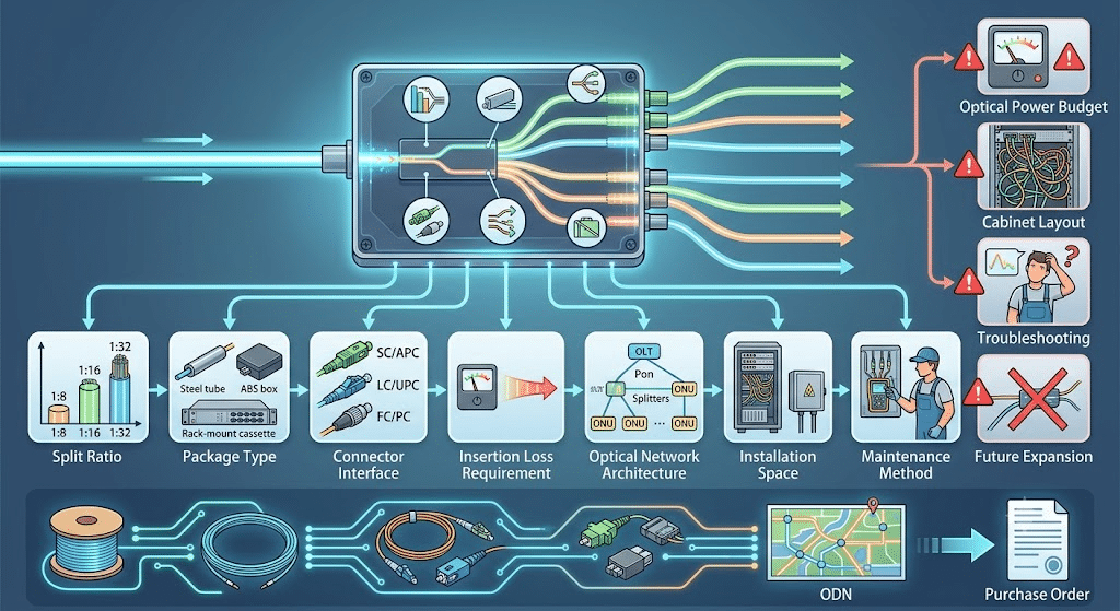
A PLC fiber optic splitter should be selected by split ratio, package type, connector interface, insertion loss requirement, optical network architecture, installation space, and maintenance method. In FTTH and passive optical networks, the splitter decides how one optical input is distributed to multiple output fibers, so the wrong selection can affect optical power budget, cabinet layout, troubleshooting, and future expansion. Buyers planning a broadband access project should evaluate PLC splitters together with fiber optic cable products, fiber optic accessories, and the actual ODN design before issuing a purchase order.
Quick Answer
Choose a PLC fiber optic splitter by confirming the required split ratio, connector type, package format, available installation space, optical power budget, and the role of the splitter in the network. The FiberCableSupplier knowledge catalog describes PLC splitters as products based on planar lightwave circuit technology, with low insertion loss, low polarization dependent loss, and high channel uniformity. It lists SC, LC, and FC connector options, with other connector types customizable. It also lists common split ratios including 1:2, 1:4, 1:8, 1:16, 1:32, 1:64, 2:2, 2:4, 2:8, 2:16, 2:32, and 2:64.
For most FTTH procurement work, the key decision is not simply “which splitter is cheapest.” The buyer must decide whether the project needs a steel tube splitter, miniature splitter, rack-mounted splitter, tray type splitter, plug-in splitter, or box splitter. The package style should match the optical distribution box, cabinet, rack, splice closure, or wall-mounted access point where the splitter will be installed.
Table of Contents
- What a PLC Fiber Optic Splitter Does
- Why Splitter Selection Matters in FTTH Networks
- PLC Splitter vs FBT Splitter
- How to Choose the Right Split Ratio
- Package Types and Installation Scenarios
- Connector Choices: SC, LC, FC, and Custom Options
- Technical Selection Table
- Procurement Checklist
- Installation and Maintenance Tips
- Common Mistakes to Avoid
- Factory Insights
- Frequently Asked Questions
- Conclusion
What a PLC Fiber Optic Splitter Does
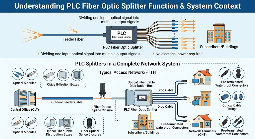
A PLC fiber optic splitter is a passive optical component used to divide an optical signal from one or two input fibers into multiple output fibers. It does not require electrical power. In a passive optical network, it allows one feeder fiber from the central office or optical line terminal side to serve multiple distribution fibers toward subscribers, buildings, rooms, or network terminals.
In the FiberCableSupplier catalog, PLC Optical Splitter appears in the fiber optic cable accessories section alongside optical modules, optical fiber cable distribution boxes, fiber optical splice closures, optical cable fittings, and pre-terminated waterproof connectors. That position is important. A splitter is rarely purchased alone. It belongs to a system that includes cable, connectors, distribution hardware, splice protection, and installation planning.
For access-network design, PLC splitters are often used with distribution boxes, cabinets, splice closures, and drop cable. A project may use outdoor cable on the feeder route, a splice closure at the branch point, a distribution box near the building, a PLC splitter inside the distribution stage, and drop cable toward the end user. If the project team is still designing the access route, FiberCableSupplier’s FTTH fiber optic cable guide and FTTH commercial broadband solutions page give useful context before selecting splitter packaging.
Why Splitter Selection Matters in FTTH Networks
Splitter selection matters because every split divides optical power. A higher split ratio may support more users, but it also creates more optical loss. A 1:64 split has a different network budget than a 1:8 split. If the splitter is selected only by subscriber count, the network may fail the optical power budget even if all cables and connectors are installed correctly.
Splitter selection also affects field work. A rack-mounted splitter may be convenient in a central office or telecom room, while a plug-in splitter may be easier to maintain in a modular distribution box. A steel tube splitter may fit compact spaces, but it may need additional protection or routing support depending on the cabinet. A tray type splitter may be suitable where splicing and organized fiber management are required together.
Buyers should treat the splitter as both an optical component and a physical installation component. The optical side includes insertion loss, polarization dependent loss, uniformity, split ratio, working wavelength, and fiber type. The physical side includes package size, connector interface, cable routing, cabinet space, mounting method, labeling, and future maintenance. Both sides matter in B2B procurement.
PLC Splitter vs FBT Splitter
PLC and FBT are two common splitter technologies. PLC stands for planar lightwave circuit. The FiberCableSupplier catalog describes PLC splitters as products based on planar lightwave circuit technology. The catalog highlights low insertion loss, low polarization related loss, and high channel uniformity. These characteristics make PLC splitters practical for many FTTH and PON distribution designs where uniform output channels are important.
FBT splitters are based on fused biconical taper technology. They can be useful in some network conditions, but PLC splitters are commonly selected where the project needs compact size, multiple output channels, and consistent splitting over larger ratios. For modern FTTH and PON deployments, buyers often evaluate PLC splitters first because split ratios such as 1:16, 1:32, and 1:64 are common in access networks.
| Item | PLC Splitter | FBT Splitter |
|---|---|---|
| Technology | Planar lightwave circuit | Fused biconical taper |
| Common use | FTTH, PON, high-count splitting, compact distribution hardware | Selected for some simpler or lower-count splitting scenarios |
| Channel uniformity | Catalog highlights high channel uniformity | Depends on design and split configuration |
| Procurement focus | Split ratio, package format, connector, loss, cabinet fit | Split ratio, wavelength, cable format, project requirement |
For standards context in passive optical networks, engineers may review ITU recommendations such as ITU-T G.984 for GPON and ITU-T G.9807.1 for XGS-PON. These references help frame the network architecture, while the splitter datasheet and project optical budget should control the actual product selection.
How to Choose the Right Split Ratio
The split ratio defines how many output paths the splitter creates. The FiberCableSupplier catalog lists common specifications including 1:2, 1:4, 1:8, 1:16, 1:32, 1:64, 2:2, 2:4, 2:8, 2:16, 2:32, and 2:64. In simple terms, a 1:32 splitter takes one input and divides it into 32 outputs. A 2:32 splitter uses two inputs and 32 outputs, which may be selected for specific network designs.
The correct ratio depends on the optical line terminal design, user density, route length, connector count, splice count, optical fiber type, and power budget. A higher ratio can reduce feeder fiber usage and support more endpoints, but it increases optical splitting loss. A lower ratio may support a stronger power budget or longer reach, but it uses more distribution resources.
| Split Ratio | Typical Planning Use | Buying Note |
|---|---|---|
| 1:2 or 1:4 | Small branches, test networks, or staged distribution | Useful when only a few outputs are needed. |
| 1:8 | Small access zones or building distribution | Balances modest output count with lower split complexity. |
| 1:16 | Medium FTTH distribution | Common where user density is moderate. |
| 1:32 | Common FTTH/PON access distribution | Often considered for broader subscriber coverage. |
| 1:64 | High-density splitting when power budget allows | Requires careful power budget confirmation. |
| 2:N splitters | Special network architectures or redundancy-related layouts | Confirm with the network designer before ordering. |
For FTTH projects, the splitter ratio should be chosen after the optical power budget is calculated. Do not select 1:64 only because it serves more users. Do not select 1:8 only because it feels safer. The right ratio is the one that fits the PON architecture, distance, connector loss, splice loss, future expansion, and service plan.
Package Types and Installation Scenarios
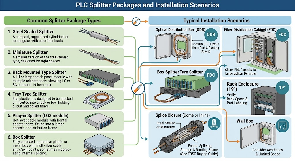
PLC splitters are available in multiple physical packages. The FiberCableSupplier catalog lists packaging dimensions for steel sealed splitters, miniature splitters, rack mounted type splitters, tray type splitters, plug-in splitters, and box splitters. This range matters because a splitter may be installed inside a rack, optical distribution box, fiber distribution cabinet, splice tray, wall box, or outdoor access enclosure.
| Package Type | Where It Is Often Used | Procurement Focus |
|---|---|---|
| Steel sealed splitter | Compact protection and embedded installation | Confirm fiber length, tube protection, and cabinet space. |
| Miniature splitter | Small enclosures and tight spaces | Check bend radius, routing room, and connector plan. |
| Rack mounted splitter | Telecom room, central office, equipment rack | Confirm rack size, port layout, labeling, and front access. |
| Tray type splitter | Splice tray or distribution tray applications | Confirm tray compatibility and fiber management. |
| Plug-in splitter | Modular optical distribution box or cabinet | Check module standard, insertion direction, and maintenance access. |
| Box splitter | Wall-mounted or cabinet-mounted distribution | Confirm enclosure size, port count, and cable exit direction. |
Package selection should be based on the installation hardware, not only the split ratio. If the splitter will be installed in an ODB, confirm the ODB layout first. If it will be installed in a rack, confirm rack space and port labeling. If it will be used with splice closures, confirm whether splicing, storage, and routing space are sufficient. FiberCableSupplier’s fiber optic splice closure buying guide is useful when splitters are part of an outdoor branch point.
Connector Choices: SC, LC, FC, and Custom Options
The FiberCableSupplier catalog states that PLC splitter connectors can provide SC, LC, and FC, and that other types can be customized. Connector selection affects installation speed, port density, compatibility with distribution hardware, and maintenance. SC is common in many access networks and optical distribution boxes. LC supports higher density in many telecom and data center environments. FC may be used in some equipment or legacy network conditions.
Connector selection should match the network interface, adapter panel, splitter package, and field technician practice. Do not mix connector types without a clear plan. Adapter conversion adds cost, loss points, and operational confusion. If the project uses pre-terminated drop cables or distribution pigtails, the splitter connector should be coordinated with those components before shipment.
For broader fiber and connector planning, it helps to consider the whole access link. A splitter may connect to feeder cable on one side and distribution or drop cable on the other. FiberCableSupplier’s bow-type drop cable for duct and tight buffer fiber pages are useful examples of related access-network components.
Technical Selection Table
| Selection Item | What to Confirm | Why It Matters |
|---|---|---|
| Split ratio | 1:2 through 1:64 or 2:2 through 2:64 | Determines output count and optical power budget. |
| Package type | Steel sealed, miniature, rack mounted, tray type, plug-in, or box | Determines installation location and maintenance style. |
| Connector | SC, LC, FC, or customized type | Must match adapter panels, cabinets, and field cables. |
| Optical performance | Insertion loss, polarization dependent loss, and uniformity | Affects network stability and budget margin. |
| Fiber type | G652D, G657A, or project requirement | Must align with the cable and access network design. |
| Working wavelength | Project operating wavelength range | Must fit the PON service plan. |
| Standards | Catalog references Telcordia GR-1209-CORE Issue 4, Telcordia GR-1221-CORE Issue 3, YD/T2000.1-2014, and ROHS | Helps procurement teams evaluate product compliance claims. |
| Installation space | Cabinet, ODB, rack, tray, box, or closure dimensions | Prevents ordering a splitter package that cannot be installed. |
Optical fiber type should be confirmed with the cable design. General single-mode fiber references such as ITU-T G.652 and bend-insensitive fiber references such as ITU-T G.657 can help engineers understand fiber categories, but the project datasheet and network budget should control final selection.
Procurement Checklist
- Confirm whether the splitter is for FTTH, FTTB, PON distribution, cabinet distribution, rack installation, or field enclosure use.
- Confirm the split ratio, such as 1:8, 1:16, 1:32, or 1:64.
- Confirm whether the project requires 1:N or 2:N splitter architecture.
- Confirm package type: steel sealed, miniature, rack mounted, tray type, plug-in, or box splitter.
- Confirm connector interface: SC, LC, FC, or customized connector.
- Confirm fiber type, pigtail length, connector polish, and cable jacket requirement.
- Confirm installation hardware, cabinet space, ODB layout, or rack layout.
- Confirm insertion loss, polarization dependent loss, uniformity, and return loss requirements.
- Confirm labeling, port numbering, and maintenance access.
- Confirm whether the splitter is ordered alone or with ODB, patch cord, pigtail, splice closure, and fiber cable.
For B2B purchasing, the best inquiry includes the ODN architecture, splitter ratio, connector type, package type, installation location, quantity, and related components. Buyers can send those details through FiberCableSupplier’s contact page or review broader project support through the support page.
Installation and Maintenance Tips
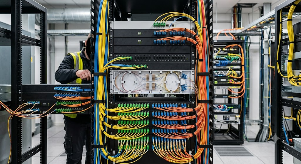
First, install the splitter where technicians can access it without disturbing unrelated fibers. A compact package is useful only if the installation still allows safe routing, labeling, cleaning, inspection, and replacement. Crowded splitter installation creates avoidable maintenance risk.
Second, keep the splitter ports clearly labeled. Splitter outputs must be easy to trace to subscriber groups, building zones, floors, rooms, or distribution fibers. Poor labeling turns a clean FTTH design into slow troubleshooting work.
Third, protect bend radius and fiber routing. Splitters are often installed in tight spaces, but tight space is not an excuse for sharp bends. The splitter package, pigtail length, and cabinet layout should allow organized routing without stress.
Fourth, clean connectors before final testing. Connector contamination can be mistaken for splitter loss. Technicians should inspect and clean connector end faces according to the project’s fiber handling procedure before judging optical performance.
Common Mistakes to Avoid
Mistake 1: Choosing Split Ratio Without a Power Budget
A high split ratio may look efficient, but it increases optical splitting loss. Always confirm the optical power budget before selecting 1:32 or 1:64 for a real network.
Mistake 2: Ignoring Package Type
A splitter with the right optical ratio can still be wrong if it does not fit the cabinet, tray, rack, or distribution box. Physical packaging should be specified together with the optical ratio.
Mistake 3: Mixing Connector Types Without a Plan
SC, LC, and FC interfaces are not interchangeable without adapters or matching hardware. Connector decisions should be coordinated across splitters, patch cords, pigtails, ODBs, and test equipment.
Mistake 4: Buying Splitters Separately from the ODN Hardware
A splitter belongs inside a physical network. If the ODB, rack, closure, pigtail, and patch cord plan are not confirmed, the splitter may arrive before the installer knows how it will be mounted and routed.
Mistake 5: Treating All PLC Splitters as Identical
PLC splitters may differ by package, connector, split ratio, fiber type, optical performance, pigtail length, and installation method. A complete RFQ should describe the real installation requirement.
Factory Insights
From a factory quotation perspective, a PLC splitter request is clearest when it includes split ratio, connector type, package type, fiber type, pigtail length, quantity, and installation hardware. A request that only says “PLC splitter 1:32” is incomplete. A better request says whether it is a 1:32 SC/APC plug-in splitter for an ODB, a rack-mounted splitter for a telecom room, or a steel tube splitter for an enclosure.
The FiberCableSupplier catalog lists PLC splitters as compact products with low insertion loss, low polarization related loss, and uniform power distribution. It also lists SC, LC, and FC connector options, common 1:N and 2:N ratios, and multiple package styles. For distributors, contractors, and ISPs, this means the quotation should define both the optical specification and the physical installation style.
In project purchasing, the splitter should be quoted with related accessories when possible. A complete passive access network may include outdoor cable, optical distribution boxes, splice closures, PLC splitters, patch cords, drop cables, and optical modules. Treating these as separate unrelated items increases mismatch risk.
Frequently Asked Questions
What is a PLC fiber optic splitter?
A PLC fiber optic splitter is a passive optical component based on planar lightwave circuit technology. It divides one or two optical inputs into multiple output fibers for FTTH, PON, and access network distribution.
What split ratios are available for PLC splitters?
The FiberCableSupplier catalog lists common ratios including 1:2, 1:4, 1:8, 1:16, 1:32, 1:64, 2:2, 2:4, 2:8, 2:16, 2:32, and 2:64.
Which connector types can PLC splitters use?
The catalog states that PLC splitter connectors can provide SC, LC, and FC, and that other connector types can be customized.
What package types are used for PLC splitters?
The catalog lists steel sealed splitters, miniature splitters, rack mounted type splitters, tray type splitters, plug-in splitters, and box splitters.
Is a 1:32 splitter always better than a 1:16 splitter?
No. A 1:32 splitter supports more outputs, but it also creates a different optical power budget. The correct ratio depends on network architecture, distance, loss budget, and service plan.
Can PLC splitters be used in FTTH networks?
Yes. PLC splitters are widely used in FTTH and passive optical distribution networks to divide optical signals from feeder fibers toward multiple distribution or subscriber paths.
What should I include in a PLC splitter quotation request?
Include split ratio, connector type, package type, fiber type, pigtail length, installation location, quantity, optical performance requirements, and related accessories such as ODBs or patch cords.
Do PLC splitters need electrical power?
No. PLC splitters are passive optical components. They distribute optical signals without requiring electrical power.
Conclusion
A PLC fiber optic splitter should be selected by network design, not by split ratio alone. The buyer should confirm the optical architecture, split ratio, package type, connector interface, fiber type, installation space, power budget, and maintenance method. For FTTH and PON projects, the splitter directly affects optical performance, cabinet layout, future troubleshooting, and network scalability.
FiberCableSupplier’s catalog-backed PLC splitter offering includes planar lightwave circuit splitter products with low insertion loss, low polarization related loss, high channel uniformity, SC/LC/FC connector options, common 1:N and 2:N ratios, and multiple package styles such as steel sealed, miniature, rack mounted, tray type, plug-in, and box splitters. Buyers should specify the complete optical and physical requirement before ordering.
Need help choosing the right fiber optic cable?
Our engineering team can recommend the best solution for your project. Contact us today for a free quotation.